Designing a Heat Exchanger: A Step-by-Step Guide for Process Engineers in Canada
- Patrick Law
- Feb 13, 2023
- 28 min read

Updated: Apr 29, 2025
Heat exchangers play a critical role in many industrial processes, particularly in the oil and gas industry. As a process engineer in Alberta, Canada, you need to understand the steps involved in designing a heat exchanger to ensure that it meets the specific needs of your project. In this article, we'll outline the general steps involved in the design of a heat exchanger.
Envelope Calculations
Calculation: Q=U*A*LMTD=m*Cp*ΔT; iterative for U
Examples:
A. (AOC) BFW/Emulsion TEMA
B. (Blackrock Orion)
C. (Cenovus, Phase 1E)
S. (Sunshine,
In Brief
1. Problem Definition: m, T, dPmax
2. Heat Transfer Analysis:
Q = U * A * LMDT;
Q[kJ/h] = m[kg/h] * Cp[J/kg·K] * ΔT[K]
U[kJ/(h·m2·K)]=estimate then iterate configuration for dPmax limit & erosion limit
A[m2] = length limited by shipping, standard tube sizes
LMTD[K] = ((T1-t2)-(T2-t1)) / ln ((T1-t2)/(T2-t1))
T1[K] = Inlet tube side fluid temperature
T2[K] = Outlet tube side fluid temperature
t1[K] = Inlet shell side fluid temperature
t2[K] = Outlet shell side fluid temperature
3. Type Selection:
Shell and Tube: High pressure, large temperature, rod-out cleaning; tubes, tube pitch, shell, headers, supports, nozzles, gaskets, baffles
Plate and Frame: High pressure drop okay, Large dT, compact
Spiral heat exchanger: Large dT, High pressure-drop
Kettle Type (reboiler): bottom of column, propane refrigeration
Double Pipe / Hairpin: simple, in pipe rack, very high pressures
Direct Contactors: desuperheating fluids
4. Thermodynamic Calculations: Heat integration Simulation software: HYSYS, Chemcad, gProms, not by hand.
5. Mechanical Design:
Shell and tube heat exchanger:
a. ASME Boiler and Pressure Vessel Code, Section VIII, Division 1
b. TEMA (Tubular Exchanger Manufacturers Association) Standards
c. API (American Petroleum Institute) 660
d. CSA B51 Boiler, Pressure Vessel, and Pressure Piping Code
Spiral heat exchanger:
a. ASME Boiler and Pressure Vessel Code, Section VIII, Division 1
b. CSA B51 Boiler, Pressure Vessel, and Pressure Piping Code
c. API (American Petroleum Institute) 660
6. Vendor Selection & Performance Testing:
Vendors:
Shell & Tube: Altex Industries, Exchanger Industries, Fabsco, Calhex, Koch
Plate & Frame: RamEx Exchanger (Alfa Laval), APV, Joule Technical Sales (ITT Industries), Cascade
Spiral: Inproheat (Tranter), Gooch Thermal Systems, Graham Manufacturing, Superior, Ram Ex
Double Pipe: Koch Heat Transfer (Brown Fintube), Alco Products, Bas Kim, RH Holland
Performance Testing: PEECO, Enerquip, Alfa Laval, Xchanger Inc., Heat Transfer Equipment, Kelvion, SPX FLOW, Chart Energy & Chemicals, CECO Environmental, SWEP International
7. Important Documentation Deliverables Used/Affected: BOD, Process Calculations, BFD, PFD, P&ID, Equipment Data Sheets, M&EB Battery Limit Table, Plot Plan, Relief Valve Sizing Calculations, Flare System Simulation, Flare, Relief and Vent Report, Control Narrative, Control Philosophy, Shut-down Key.
Step 1: Problem Definition
The first step in designing a heat exchanger is to identify the process requirements and constraints. This includes determining, as a minimum, the heat transfer rate, the temperature difference, and the maximum allowed pressure drop. Understanding these requirements will help you determine the size and type of heat exchanger that you need.
Minimum Required Data:
m, Fluid Flow Rates (OR Heat Transfer Rate, Q)
Tx, Fluid Temperatures
deltaPmax, Maximum Allowable Pressure Drop
Fluid Chemistries / fouling factors
Other Project Management Documents
DBM, Design Basis Memorandum
PEP, Project Execution Plan
Project/Process Design Basis
Other Job Instructions (e.g., equipment numbering)
DCQP, Deliverable Quality Control Plan
Engineering Hour Estimates
Regulatory Constraints
Sources of Process Data
Block Flow Diagram
Process Flow Diagram
Heat and Material Balance
P&IDs
Line Designation Table
Plant Layout / Plot Plan
Process Simulations
Equipment Data Sheets
Instrument Data Sheets
HAZOP/RAM/What If Studies
Piping Specification
Instrumentation Specification
Step 2: Heat Transfer Analysis
Once you have a clear understanding of the process requirements, the next step is to determine the heat transfer rate, the heat transfer area, and the heat transfer coefficient. This involves using heat transfer equations and correlations based on the fluid properties, flow conditions, and the type of heat exchanger.
Heat transfer Rate, Q = m * Cp * ΔT
m = fluid flow rate, (kg/s)
Cp = heat capacity (J/kg°C)
ΔT = fluid temperature change (°C)
Heat Transfer Area, A = Q / (U * LMTD);
Where: A = Heat transfer area (m^2); length limited by shipping, # tubes limited by vessel economic size Q = Heat transfer rate (W) = m*Cp*ΔT m = fluid flow rate, (kg/s) Cp = heat capacity (J/kg°C) ΔT = fluid temperature change (°C) U = Heat transfer coefficient (W/m^2°C) (ref: API 660, TEMA standards) LMTD = Logarithmic mean temperature difference (°C) = (T1_in - T1_out) - (T2_in - T2_out) / ln((T1_in - T1_out) / (T2_in - T2_out)) T1_in = Inlet temperature of fluid 1 (°C or °F) T1_out = Outlet temperature of fluid 1 (°C or °F) T2_in = Inlet temperature of fluid 2 (°C or °F) T2_out = Outlet temperature of fluid 2 (°C or °F)
Although it is better to use a simulation fluid package and software for the fluid, it may be important to perform preliminary calculations using typical values. Here is a table of typical heat capacities:

Here is a table of typical overall heat transfer coefficient (U) estimates for different services:

Note that these are rough estimates and that actual U values will depend on a number of factors, such as flow rates, pressure drops, temperatures, fouling factors, and the geometry of the heat exchanger.
Some references for where to get information on typical overall heat transfer coefficient values include:
"Heat Exchanger Design Handbook" by Kuppan Thulukkanam
"Process Heat Transfer" by D.Q. Kern
"Heat Exchangers: Selection, Rating, and Thermal Design" by Sadik Kakaç and Hongtan Liu
"Heat Transfer Handbook" by Adrian Bejan
Additionally, many heat exchanger manufacturers provide heat transfer coefficient data for their products, which can be useful in selecting and sizing a heat exchanger for a specific application.
Maximum Allowable Pressure Drop, dPmax
The maximum allowable pressure drop, similar to piping, is an economic calculation. Typical for industrial applications of shell and tube TEMA exchangers the maximum allowable pressure drop for water like liquids could be 5 to 20kPa per meter of exchanger length to create a balance between exchanger area and pumping requirements (e.g., shell side 70kPa, tube side for the higher fouling liquid 120kPa). Gas service 10 to 30kPa per meter of effective length. Plate and frame pressure drop can be slightly higher for liquid service, from 10 to 30kPa per meter of exchanger length; for plate and frame for gases, the maximum allowable pressure drop could be 20 to 50 kPa per meter of exchanger length (100kPa to 180kPa).
References:
Effectively Design Shell-and-Tube Heat Exchangers by Rajiv Mukherjee
Heat Exchanger Design Handbook, by Kuppan Thulukkanam
Plate Heat Exchanger: Design, Selection, and Application, by B. Thiessen and J. Sands
Handbook of Heat Transfer Fundamentals, edited by W.M. Rohsenow, J.P. Hartnett, and Y.I. Cho
Process Heat Transfer, by D.Q. Kern
Heat Exchanger Design Guide: A Practical Guide for Planning, Selecting and Designing of Shell and Tube Exchangers, by R.W. Serth
Exchanger Dimensions
The surface area per unit volume is an important parameter in the design and sizing of heat exchangers. For shell-and-tube exchangers, this value is typically in the range of 50-100 m^2/m^3, meaning that for a given volume of the exchanger, there is a relatively smaller surface area available for heat transfer. This is due to the larger size and complexity of shell-and-tube exchangers, which have a bundle of tubes inside a cylindrical shell. In contrast, compact exchangers such as plate-fin exchangers have a much higher surface area per unit volume, typically around 500 m^2/m, due to their compact design and the high number of fins or plates used for heat transfer. This results in a higher overall heat transfer coefficient and greater efficiency in heat transfer, making compact exchangers a popular choice for many applications where space and weight are important factors.
(ref: Hewitt, G. F., & Pugh, S. J. (2007). Approximate design and costing methods for heat exchangers. Heat transfer engineering, 28(2), 76-86.)
The typical L/D (length-to-diameter) sizes of heat exchangers vary widely depending on the specific application and design requirements. For shell-and-tube exchangers, the L/D ratio can range from 3:1 to 8:1, with a common value of 6:1. This allows for sufficient heat transfer area while maintaining an efficient and compact design. For plate-type exchangers, the aspect ratio (L/W, length-to-width) is typically much higher, ranging from 10:1 to 30:1, due to the thin and flat nature of the plates.
These values are based on industry standards and best practices. For example, the Tubular Exchanger Manufacturers Association (TEMA) provides guidelines and standards for the design and sizing of shell-and-tube heat exchangers, including recommended L/D ratios based on the specific application and type of exchanger. Other sources of information on heat exchanger design and sizing include textbooks and engineering handbooks such as "Heat Exchanger Design Handbook" by Kuppan Thulukkanam and "Process Heat Transfer" by D.Q. Kern.
Fouling Factors
The fouling factor is applied to the overall heat transfer coefficient (U) in a shell and tube heat exchanger design. The overall heat transfer coefficient represents the rate of heat transfer per unit area of the heat transfer surface, and it includes contributions from both the convective heat transfer coefficient (h) and the conductive heat transfer resistance (R). The overall heat transfer coefficient is expressed as:
U = 1 / ((1 / h_i) + R + (1 / h_o))
h_i is the convective heat transfer coefficient on the inside of the tube
h_o is the convective heat transfer coefficient on the outside of the tube
R is the conductive heat transfer resistance.
The fouling factor represents an additional resistance to heat transfer caused by the buildup of deposits on the heat transfer surfaces, and it is typically expressed in units of m2·K/W or ft2·°F·hr/Btu. The fouling factor can be incorporated into the overall heat transfer coefficient by adding it to the conductive heat transfer resistance term in the equation above, as follows:
U = 1 / ((1 / h_i) + R + Fouling Factor + (1 / h_o))
By adding the fouling factor to the conductive heat transfer resistance, the overall heat transfer coefficient is reduced to account for the additional resistance to heat transfer caused by fouling. This allows for more accurate predictions of the heat transfer rate and the size of the heat exchanger required to achieve a desired heat transfer rate.
Overall, the fouling factor is an important consideration in the design and operation of a shell and tube heat exchanger, and it must be incorporated into the overall heat transfer coefficient to accurately predict the heat transfer performance of the exchanger.
Consider maintenance and cleaning procedures on fouling factors: This may involve designing the exchanger with features such as removable tube bundles, access ports, and clean-in-place (CIP) systems to facilitate maintenance and cleaning.
Perform simulations and analysis: To ensure that the shell and tube exchanger is optimized for maximum heat transfer efficiency and minimal fouling, simulations and analysis can be performed using software tools such as Aspen HYSYS or PRO/II. These simulations can provide valuable insights into the expected performance of the exchanger under different operating conditions, as well as the potential for fouling and its impact on heat transfer efficiency
Budgetary Cost Estimate - Heat Exchangers
Back-of-Envelope Calculation: Purchase Cost per unit, FOB, USD = (1+F) * A * C * modularization factor (ref: TEMA guidelines)
A, Area in ft2
F, fabrication factors (ref: TEMA):
Carbon Steel: 1.0
Stainless Steel: 2.0
High Alloy Metals: 3.0
modularization factor ~ 4 (ref: Simplified Hand Calculation)
C, construction factors (ref: TEMA):
2.0 for a standard design with no special features or materials
2.5 for a more complex design with additional features or special materials
3.0 or higher for a highly customized or specialized design
Note: Typical installation factor could be 2.5 to 4 for installed cost
Additional References
"Heat Exchanger Design Handbook" by Kuppan Thulukkanam and "Process Heat Transfer" by D.Q. Kern
Peters/Timmerhaus: http://www.mhhe.com/engcs/chemical/peters/data/ce.html Matches: https://www.matche.com/equipcost/Default.html Simplified Hand Calculation: https://www.seas.upenn.edu/~dlewin/CACHE_Workshop/LECTURE_06_Equipment_Sizing_and_Capital_Cost_Estimation.pdf) Hand Calculation by 1984 article: https://www.cheresources.com/invision/blog/4/entry-278-shell-and-tube-heat-exchanger-cost-estimation/
Example Calculation
Suppose you have a cross-flow shell and tube heat exchanger that needs to transfer heat from fluid 1 to fluid 2. The heat transfer rate, Q, is 10,000 W, the heat transfer coefficient, U, is 100 W/m^2°C, and the logarithmic mean temperature difference, ΔT, is 30°C. The heat transfer area, A, can be calculated as follows: A = Q / (U x ΔT) A = 10,000 / (100 x 30) A = 10 / 3 A = 3.33 m^2 Therefore, the heat transfer area of the shell and tube heat exchanger is 3.33 m^2. This is just an example calculation, and the actual heat transfer area will depend on the specific requirements of your process. However, this equation provides a starting point for calculating the heat transfer area of a shell and tube heat exchanger. Using a software like HYSYS, the style and size of a heat exchanger can be optimized for a process.
Step 3: Selection of Heat Exchanger Type
The next step is to choose the appropriate heat exchanger type based on the heat transfer requirements, the available space, and the cost. The most common types of heat exchangers are shell and tube, plate and frame, and spiral. Each type has its own strengths and weaknesses, so it's important to choose the one that's best suited to your specific needs.
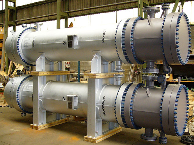
Shell and Tube: High pressure, large temperature, rod-out cleaning
This is the most common type of heat exchanger used in many industrial processes. It consists of a shell that contains tubes through which the two fluids flow. This type of heat exchanger is well-suited for high-pressure applications and is capable of handling large temperature differences. TEMA Class R: This standard covers rear-head type heat exchangers, which are typically used for high-pressure applications. TEMA Class B: This standard covers U-tube type heat exchangers, which are typically used for applications where one fluid is at a high temperature and the other is at a low temperature. TEMA Class C: This standard covers fixed-tubesheet type heat exchangers, which are typically used for applications where both fluids are at high temperatures or where the fluids are corrosive or toxic. TEMA Class N: This standard covers floating-head type heat exchangers, which are typically used for applications where one fluid is at a high temperature and the other is at a low temperature. Floating-head type heat exchangers are good for being able to remove the tube bundle for inspection.
References:
Heat Exchanger Design Handbook, by Kuppan Thulukkanam
Process Heat Transfer, by D.Q. Kern
Heat Exchangers: Selection, Rating, and Thermal Design, by Sadik Kakac, Hongtan Liu, and Y.W. Lee
Mechanical Design of Heat Exchangers and Pressure Vessels, by R.W. Serth
Handbook of Heat Transfer Fundamentals, edited by W.M. Rohsenow, J.P. Hartnett, and Y.I. Cho
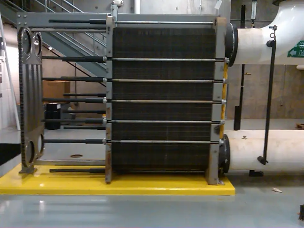
Plate and Frame: High pressure drop okay, Large dT, compact
This type of heat exchanger consists of a series of thin metal plates that are stacked to form a compact unit. The two fluids flow between the plates, transferring heat from one fluid to the other. Plate and frame heat exchangers are well-suited for applications where the fluids have a large temperature difference and are compatible with a high-pressure drop. They are cheapest where gasket issues do not present a hazard or difficulties.
References:
Thermaxx Jackets. (n.d.). Plate Frame Heat Exchangers Explained. [Blog post]. Retrieved from https://blog.thermaxxjackets.com/plate-frame-heat-exchangers-explained
European Heat Exchanger Designers' Association (EHEDG) Guidelines: This organization provides guidelines for the design, fabrication, and testing of plate and frame heat exchangers, including information on heat transfer coefficients.
Alfa Laval Plate Heat Exchanger Design Handbook: This handbook provides design guidelines for plate and frame heat exchangers, including information on heat transfer coefficients for various fluid types, flow conditions, and heat exchanger geometries.
Gasketed Plate Heat Exchanger Design Principles: This publication provides design principles for gasketed plate heat exchangers, including information on heat transfer coefficients for various fluid types, flow conditions, and heat exchanger geometries.
Plate Heat Exchanger: Design, Selection, and Application: This book provides comprehensive information on plate and frame heat exchangers, including information on heat transfer coefficients for various fluid types, flow conditions, and heat exchanger geometries.
Spiral heat exchanger: Large dT, High pressure-drop.
This type of heat exchanger consists of two concentric spirals that are separated by a thin metal plate. The fluids flow through the spirals, transferring heat from one fluid to the other. Spiral heat exchangers are well-suited for applications where the fluids have a large temperature difference and are compatible with a high-pressure drop.

References:
Design and Analysis of Spiral Heat Exchangers, by R.K. Shah and D.R. Sekulib
Spiral Heat Exchangers: Theory, Design, Manufacture and Use, by J.R. Thome
Handbook of Heat Transfer Fundamentals, edited by W.M. Rohsenow, J.P. Hartnett, and Y.I. Cho
"Spiral Heat Exchangers: An Overview" by Thermaxx Jackets, https://blog.thermaxxjackets.com/spiral-heat-exchangers-explained
"Spiral Heat Exchangers: Advantages, Applications, and Design Considerations" by Heat Transfer Solutions, https://heattransfersolutions.com/spiral-heat-exchangers.
Double-pipe: small duties because it is manufactured from standard components
Plate-fin and printed circuit: where space is more costly than premium (e.g., off-shore, existing facilities)


Brazed Aluminum: low temperatures, clean service

Step 4: Thermodynamics Calculations
Conduct thermodynamics calculations to determine the pressure drop, the heat transfer rate, and the outlet temperatures of the fluids. This involves using energy and mass balance equations to calculate these parameters.
*This step is usually done in a thermodynamic calculation software like HYSYS by Aspentech (best), Chemcad, gProms. The steps to simulating are to choose a fluid package, set up the chemistry and thermodynamic conditions, and the software will calculate the thermodynamic conditions required for the exchanger.
Simple Hand Calculation Examples: https://www.pdhonline.com/courses/m371/m371content.pdf
Thermodynamic Calculation Hand Example
Question: Suppose you have a cross-flow shell and tube heat exchanger with fluid 1 at an inlet temperature of 80°C and an outlet temperature of 60°C, and fluid 2 at an inlet temperature of 40°C and an outlet temperature of 50°C. The flow rate of fluid 1 is 0.05 kg/s, and the flow rate of fluid 2 is 0.03 kg/s. Answer: The first step in the calculation is to determine the logarithmic mean temperature difference, ΔT. This can be calculated using the following equation: ΔT = (T1_in - T1_out) - (T2_in - T2_out) / ln((T1_in - T1_out) / (T2_in - T2_out)) Where: T1_in = Inlet temperature of fluid 1 (°C) T1_out = Outlet temperature of fluid 1 (°C) T2_in = Inlet temperature of fluid 2 (°C) T2_out = Outlet temperature of fluid 2 (°C) Plugging in the given values, we get: ΔT = (80 - 60) - (40 - 50) / ln((80 - 60) / (40 - 50)) ΔT = 20 - (-10) / ln(20 / -10) ΔT = 30 / ln(2) ΔT = 30 / 0.693 ΔT = 43.05°C Next, we can calculate the heat transfer rate, Q, using the following equation: Q = m_1 * c_p * (T1_in - T1_out) Where: m_1 = Flow rate of fluid 1 (kg/s) c_p = Specific heat capacity of fluid 1 (J/kg°C) Plugging in the given values, we get: Q = 0.05 * 4.18 * (80 - 60) Q = 0.05 * 4.18 * 20 Q = 4.18 * 20 Q = 83.6 W Finally, we can calculate the outlet temperatures of fluid 1 and fluid 2 using the following equations: T1_out = T1_in - Q / (m_1 * c_p) T2_out = T2_in + Q / (m_2 * c_p) Where: m_2 = Flow rate of fluid 2 (kg/s) c_p = Specific heat capacity of fluid 2 (J/kg°C) Plugging in the given values, we get: T1_out = 60°C T2_out = 50°C In this example, we calculated the logarithmic mean temperature difference, ΔT, and the heat transfer rate, Q, for a cross-flow shell and tube heat exchanger. We also calculated the outlet temperatures of fluid 1 and fluid 2. It's important to keep in mind that this is just an example calculation, and the actual results will depend on the specific requirements of your process. However, this example provides a starting point for performing thermodynamics calculations for a shell and tube heat exchanger.
By conducting thermodynamics calculations, you can determine the performance of the heat exchanger and ensure that it meets the process requirements. This information can then be used to optimize the design of the heat exchanger for improved performance and efficiency.
Step 5: Mechanical Design
Once the thermodynamics calculations are complete, next step is to specify the size and material of the heat exchanger components. This includes the tubes, the shell, the headers, and the supports. The mechanical design must meet the process requirements, the safety codes, and the industry standards.
Here is a list of some of the most common mechanical design parameters:
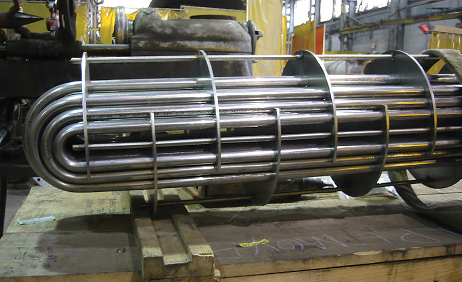
Tubes: The size, material, and arrangement of the tubes in the heat exchanger need to be specified. The tube size will affect the pressure drop and heat transfer rate, while the material will affect the durability and corrosion resistance of the heat exchanger.
Shell: The size and material of the shell need to be specified. The shell size will affect the available heat transfer area, while the material will affect the durability and corrosion resistance of the heat exchanger.
Headers: The size and material of the headers, which connect the tubes to the shell, need to be specified. The headers play a crucial role in distributing the fluid evenly across the heat transfer area and must be designed to withstand the pressure and temperature conditions.
Supports: The size and material of the supports, which hold the tubes in place, need to be specified. The supports must be designed to withstand the weight of the tubes and any thermal expansion that may occur.
Nozzles: The size and location of the nozzles, which provide the inlet and outlet for the fluid, need to be specified. The nozzles must be designed to accommodate the flow rate and pressure of the fluid and to minimize the pressure drop.
Gaskets: The type and material of the gaskets, which are used to seal the nozzles and headers, need to be specified. The gaskets must be designed to withstand the temperature and pressure conditions and to prevent leaks.
Baffles: The size, spacing, and material of the baffles, which are used to direct the fluid flow and to prevent short-circuiting, need to be specified. The baffles must be designed to maximize the heat transfer and to minimize the pressure drop.
The design codes for shell and tube heat exchangers and spiral heat exchangers in Alberta, Canada, are generally based on the standards set by the American Society of Mechanical Engineers (ASME) and the Canadian Standards Association (CSA). Here is a list of the most common design codes for these types of heat exchangers:
Shell and tube heat exchanger:
a. ASME Boiler and Pressure Vessel Code, Section VIII, Division 1
b. TEMA (Tubular Exchanger Manufacturers Association) Standards
c. API (American Petroleum Institute) 660
d. CSA B51 Boiler, Pressure Vessel, and Pressure Piping Code
Spiral heat exchanger:
a. ASME Boiler and Pressure Vessel Code, Section VIII, Division 1
b. CSA B51 Boiler, Pressure Vessel, and Pressure Piping Code
c. API (American Petroleum Institute) 660
It's important to note that these are the most common design codes and the specific codes that apply to your heat exchanger will depend on the requirements of your process and the regulations in your jurisdiction. It's recommended to consult with a licensed engineer who is familiar with the regulations in your province in Canada, to determine the applicable design codes for your heat exchanger.
Step 6: Performance Testing
To ensure that the heat exchanger is functioning as intended, it's important to conduct performance testing. This involves verifying the heat transfer rate and the pressure drop and comparing the results with the design predictions. This step is crucial in validating the design of the heat exchanger.
The performance testing of industrial scale shell and tube heat exchangers in the Alberta oil-patch can be conducted by several companies, including:
Process Engineering and Equipment Company (PEECO)
Enerquip
Alfa Laval
Xchanger Inc.
Heat Transfer Equipment
Kelvion
SPX FLOW
Chart Energy & Chemicals
CECO Environmental
SWEP International
These are some of the most well-known companies that specialize in the performance testing of shell and tube heat exchangers in the Alberta oilpatch. They have extensive experience in the design, fabrication, and testing of heat exchangers and can provide reliable and accurate results. When selecting a company for performance testing, it's important to consider their reputation, experience, and expertise in your specific industry and to ask for references and case studies.
Step 7: Documentation
The final step in the design process is to prepare detailed documentation of the heat exchanger design. This includes the process requirements, the heat transfer calculations, the material specifications, and the performance test results. This documentation will serve as a reference for future reference and maintenance of the heat exchanger.
Here is a list of all of the process deliverables that may be required of a process engineer with those that are applicable to a heat exchanger in (bold):
Process Engineering Documents
BOD
Battery Limit Table
BFD
Catalyst/Chemical Requirements
Emissions and Effluent Summary
Equipment Sizing Report
Flare System Simulation
Flare, Relief and Vent Report
Hazard Assessment
HAZOP Action/Parking Lot Close Out Report
Hydraulic Analysis/Calculations
Line Sizing Summary Table
Mass & Energy Balance (M&EB)
Material Selection Process Input Table
P&IDs
Process Description
PFD
Process Simulation
Relief Valve Sizing Calculations
Utility Balances
Process Inputs to Mechanical Documents
Equipment List
LDT (Line Designation Table)
Equipment Data Sheets & Specifications
Material Selection Diagrams (MSD)
Cathodic Protection Plan & Drawings
Material Selection Report
Specialty Items List
General Arrangement Drawings
Performance Test Reports
Inspection Reports
Maintenance log
Calibration report
Material certifications
3-D models
Inputs to Piping/Civil/Structural
Fugitive Emissions Study
Area Classification Drawing
Development Area Plan
Heat Tracing Schedules
Hydro Test Plan
LDT (Line Designation Table)
Pipeline Alignment Drawings
Pipeline Bend Schedule
Pipeline Crossing Plan
Pipeline Elevation / Profile Drawings
Plot Plan
Tie-in List
3-D Model & Model reviews
Inputs to Instrumentation and Control Documents
Control Narrative
Control Philosophy
Control system Engineering & Design
Instrumentation Data Sheets
Instrument Sizing Calculations
Instrument Index
Master Alarm & Set Point Data
Safety, Fire & Gas Design
Layout Drawings & P&IDs
Shut-down Key
SIL Review
Examples
Emulsion / BFW Exchanger, 10,000bbl/day SAGD, 1.1SWR, 3.53SOR
1. Problem Definition (Project Scoping, Study)
[Client] Scope of Work (SOW)
Emulsion / BFW Exchanger, 10,000bbl/day SAGD, 1.1SWR, 3.53SOR
Location and/or Plot Plan
Existing Drawings & Specifications (BFD, PFD, P&IDs, Line List, SDK, Process Description and/or Control Philosophy incl. outside of the limits but bordering scope is relevant for process engineers)
[Engineering] Design Basis Memorandum (DBM) (IFA)
Site Data Sheet (ref: Alberta Building Code, data from Environment Canada)
Utility Systems Information = wash water, TEG glycol heating/cooling, air, gas, other
Battery Limits / Table (P, T, F)
Mechanical Design Philosophies = ASME B31.3, ASME Boiler and Pressure Vessel codes, TEMA, API guidelines.
Design Life = nominal design 30 years
Reliability/Availability/Sparing/Bypass/Isolation Philosophies = Emulsion / BFW exchangers critical equipment (sparing for cleaning not required), plant 93% availability, no bypass, double block and bleed/spades required. Exchanger cleaning during maintenance.
Operating Philosophy / Operator Availability = monitored 24/7, maintenance available 5-days per week
Insulation & Heat Tracing Philosophy = 15C
Firefighting equipment and guidelines = fire suppression system available
Oil/gas/emulsion characterizations = Lab assay, sour service, NACE required
Key Software - HYSYS, Flarenet, HTRI (preliminary exchanger design), Predict (Honeywell) for corrosion rate calculations, Compress for pressure vessels design check.
Applicable Code and Standards List: Codes, Regulation, Standards and Regulations = typical per DBM (ref: see previous projects, includ. APEGA guidelines, Professional Practice Management Plan & internal documents)
Block Flow Diagrams, BFDs
Project Specification
Engineering Deliverables List (ref: SOW,
Engineering Studies
[Engineering] Project Execution Plan, PEP
Scope of Work (incl. Deliverables List, number of issues)
Project Management Philosophy
Project Organization Chart
Procedures (work schedule, location, travel, meeting minutes, project initiation, close-out)
Project Execution Plans
Communication Plan
Doc. Control Plan
Change Management Plan
Reporting Schedule Plan
Estimating Plan
Risk Management Plan
Engineering Plan
Engineering person-hour estimate
Engineering Schedule
Risk Register
Order of Magnitude Estimate: This is the least detailed estimate that provides an approximate cost range based on limited project information. It is typically accurate within +/- 50% of the final cost.
2. Heat Transfer Analysis (Pre-FEED)
Simulation & Simulation Calculation (ref: Engineering DBM/PEP)
BFW characterization (ref: ASME Boiler and Pressure Vessel Code, NFPA codes, packaged boiler)
Design Basis Tables & Calculation (ref: Client SOW, Engineering DBM/PEP, Simulation)
PFDs & Heat and Material Balance (IFR) (ref: Simulation & Simulation Calculation)
m_BFW = 384435kg/hr (30% turndown from design rate)
m_Emulsion = 384435kg/hr (30% turndown from design rate)
Cp_BFW, Specific Heat in/out = 4.216 to 4.478kJ/(kgC) [average = 4.347kJ/(kgC)]
Cp_Emulsion, Specific Heat in/out = 4.26 to 3.87kJ/(kgC)
T1_in, BFW = 102.3C
T1_out, BFW = 196.3C
ΔT1, BFW = 196.3 - 102.3C = 94C
T2_in, Emulsion = 208C
T2_out, Emulsion = 137C
ΔT1, Emulsion = 208 - 137 = 71C
Q, Design Duty = m_BFW * Cp_BFW * ΔT1 = 272260kg/hr * 4.347kJ/(kgC)] * 94C = 111250336.7kJ/hr = 30.9MW
Sparing: 1 x 100% (ref: DBM per Reliability and Availability)
Tagging (ref: DBM or Engineering Guidelines)
Plot Plan (IFR) (ref: Client SOW, Engineering DBM/PEP, PFDs, , GAP Spacing requirements per API and ASME standards (e.g., API RP 752), local/provincial building codes) (
Process Control Narrative (ref: PFDs, Heat and Material Balance, PFDs)
Design Pressure / Design Temperature Diagram and Tables (ref: DBM, Simulation, PFD & Heat and Material Balance)
Material Selection Process Input Table
Material Selection Diagrams & Material Selection Report
Regulatory Data (ref: Simulation & Simulation Calculation, DBM, PFD & Heat and Material Balance) - Air emissions, electrical load list, water use, chemical use
Process Person-Hours Plan (ref: previous projects, DBM, PEP)
Cathodic Protection Plan & Drawings
3. Selection of Heat Exchanger Type (Pre-FEED)
Process Design Basis & Guidelines
Process Engineering Guidelines (ref: previous projects in similar service and/or client directives, standards, codes & guidelines)
Fouling factors
Emulsion fouling factor = 0.5283 (m2-°C/ kW) (ref: previous projects or client)
Boiler Feed Water, BFW = 0.1761 (m2-°C/ kW) (ref: previous projects or client)
Note 1: Allowing extra for fouling has not been effective as the organic fouling tends to build so fast that this does not increase reliability. Rather than increasing fouling allowances, the exchanger should be designed to minimize pressure drop (<75 kPa). Additional exchanger area should be based on fouling factor rather than extra duty percentage.This provides a better balance with respect to velocities, transfer coefficients, and mechanical design (such as baffle spacing).In heavy oil and produced water service, the fouling factors should not be overly conservative as excessive surface area will increase the fouling (less velocity to keep surfaces clean through erosion of deposits).Cold counter flow temperatures will be avoided as it tends to reduce the effective area through local chilling and thereby causing the heavy oil to set upon the cooler surfaces. (ref: previous projects)
Note 2: Shell and tube exchangers in PW and Emulsion service are to utilize a minimum of 1" diameter tubes. These will minimize pressure drop and reduce carbonate scaling. In addition, try to avoid control valves that cause a pressure drop just upstream of the exchanger. Shell and tube exchangers in the produced water or emulsion service should use a minimum of 1-inch diameter tubes.For shell and tube exchangers in all other services, a minimum of ¾-inch diameter tubes can be used. (ref: previous projects)
Note 3: Ideally, fluids that have a propensity to scale will be on tube side (allows tube side to be mechanically cleaned). (ref: previous projects)
Note 4: If an existing exchanger needs to be rerated and a lower or higher fouling factor is desired, then this can be evaluated on an individual basis. (ref: previous projects)
Note 5: Extra duty will not be required in addition to the calculated process duty by the process engineer to limit doubling up on exchanger duty requirements by vendor (ref: previous projects)
Note 6: The following fluids are generally placed on the tube side: water and steam or highly corrosive fluids, excessive fouling fluids, high pressure or temperature services. The following fluids are generally placed on the shell side: condensing and reboiling hydrocarbons, critical pressure drop services. (ref: previous projects)
Note 7: For shell and tube exchangers, standard shell sizes range from 305 to 1520 mm (12 to 60 inches) in diameter. Sizes below 305 mm (12 inches) are not competitive with double pipe units. (ref: previous projects)
Process Description
Equipment Sizing Basis (ref: DBM, Process Engineering Guidelines, previous projects, client preferences, Process Description)
Type: Shell and Tube
Emulsion in tubes / BFW in shell
Design: Tube-side: 300 ANSI Design, Design Pressure to match emulsion pipeline MOP
1” Tubes for emulsion service, maintain velocity to reduce fouling concerns
Shell-side: 300 ANSI
10% Excess Area
Design Rate Basis: Maximum Inlet Emulsion Rate + 0% Design Margin
Tube: Maximum BFW Rate + 0% Design Margin
Sparing = 1 x 100%
Process Engineering Sizing Calculation
m_BFW = 384435kg/hr (30% turndown from design rate)
m_Emulsion = 384435kg/hr (30% turndown from design rate)
Cp_BFW, Specific Heat in/out = 4.216 to 4.478kJ/(kgC) [average = 4.347kJ/(kgC)]
Cp_Emulsion, Specific Heat in/out = 4.26 to 3.87kJ/(kgC)
T1_in, BFW = 102.3C
T1_out, BFW = 196.3C
ΔT1, BFW = 196.3 - 102.3C = 94C
T2_in, Emulsion = 208C
T2_out, Emulsion = 137C
ΔT1, Emulsion = 208 - 137 = 71C
Q, Design Duty = m_BFW * Cp_BFW * ΔT1 = 272260kg/hr * 4.347kJ/(kgC)] * 94C = 111250336.7kJ/hr = 30.9MW
U, Overall Heat Transfer Area = estimate then iterate configuration for dPmax limit & erosion limit = estimate 300W/(m2·C) = 1080kJ/(hr·m2·C) (ref: previous projects, heat transfer literature)
LMTD, Log Mean Temperature = ((T2_in - T1_out) - (T2_out - T1_in)) / ln ((T2_in - T1_out)/(T2_out - T1_in)) = ((208 - 196.3) - (137 - 102.3)) / ln ((208 - 196.3)/(137 - 102.3)) = 21.16C
F, LMTD correction factor = 0.9 (ref: Shell and Tube Heat Exchangers - Basic Calculations.pdf)
A, Area (Gross) = Q / (U * F * LMTD) = 111250336.7kJ/hr / (1080kJ/(hr·m2·C) * 21.16C * 0.9) = 5410m2
Margin of safety, Area = 10% * A = 541m2
Total Estimated Area = 5951m2
L, Length estimate = 16ft = 4.8768m (ref: based on previous projects)
D, shell diameter estimate = 60in = 1.524m (ref: previous projects)
d, tube diameter estimate = 1in nominal = 1.315" OD = 0.033401m OD
a, tube surface area = pi*d*L = 3.1415926 * 0.033401m * 4.8768 m = 0.5117m2
n, number of tubes required (estimate) = A / a = 5951m2 / 0.5117m2 = 11629 tubes
N, number of shells required (estimate) = 11629 / 2000 = ~6 (ref: based on ~2000 tubes for 60in diameter vessel per experience)
Area per exchanger = 5951m2 / 6 = 992m2 = 10672.64 square feet
Budgetary Cost Estimate Calculation (ref: Simplified Hand Calculation: https://www.seas.upenn.edu/~dlewin/CACHE_Workshop/LECTURE_06_Equipment_Sizing_and_Capital_Cost_Estimation.pdf)
Area per exchanger = 5951m2 / 6 = 992m2 = 10672.64 square feet
Pressure, kPag = 4200kPag = 4301kPaa = 610psia
Fp = 0.9803 + 0.018*(pressure, psia/100) + 0.0017*(pressure, psia/100)^2 = 0.9803 + 0.018*(610psia/100) + 0.0017*(610psia/100)^2 = 1.15
Fl , 16ft tube length = 1.05 (ref: from table in reference)
Fm = a + (A/100)^b = 1.75 + (10673/100)^0.13 = 3.59
a, Carbon Steel / Stainless Steel = 1.75
b, Carbon Steel / Stainless Steel = 0.13
Cb, floating head = exp(11.667-0.8709*ln(Area per exchanger, ft2)+0.09005*ln(Area per exchanger, ft2)^2) = exp(11.667-0.8709 * ln(10672.64ft2) + 0.09005 * ln(10672.64ft2)^2) = $83817 USD
CP, purchase cost per exchanger = Fp x Fm x Fl x Cb = 1.15 x 3.59 x 1.05 x 83817USD = $363,340
CBM, Total Installed Cost / Bare-module cost per unit = 3.291 * CP = 3.291 * 363340 = $1.2MM USD per unit
Total Installed Cost = $1.2MM USD per unit * 6 units = $7.2MM USD = $9.5MM CAD
Back of Envelop Calculation
Purchase Cost, per shell = (1+F) * A in ft2 * C * installation factor = (1+2.0) * 10000ft2 * 2.5 * 4 = $300,000 USD per shell
F, material factor = 1.0 Carbon Steel, 2.0 SS, 3.0 High Alloy
C, construction & installation factor = 2.0 STD, 2.5 complex, 3.0 specialty
modularization factor = 4
Total Cost, FOB = $0.3MM USD * 6 = $1.8MM USD
Total cost Installed = Installation factor * Total Cost, FOB = 3.5 * $1.8MM = $6.3MM USD = $8.3MM CAD
Alternate estimate (ref: Matches)
Bare-module cost per unit, FOB, Gulf Coast USA = $852,700 USD per unit
Bare-module cost, FOB, Gulf Coast USA = $0.85MM USD per unit * 6 = $5.1MM USD = $6.8MM CAD
Total Installed Cost = (1 + direct field labour factor + indirect expenses) * Bare-module cost = (1 + 0.63 + 0.947) * $6.8MM CAD = $17.5MM CAD
Additional references:
Peters/Timmerhaus: http://www.mhhe.com/engcs/chemical/peters/data/ce.html
Simplified Hand Calculation: https://www.seas.upenn.edu/~dlewin/CACHE_Workshop/LECTURE_06_Equipment_Sizing_and_Capital_Cost_Estimation.pdf)
Hand Calculation by 1984 article: https://www.cheresources.com/invision/blog/4/entry-278-shell-and-tube-heat-exchanger-cost-estimation/
Request for Budgetary Estimates from major Vendors (ref: Process Data Sheet, Equipment Sizing Basis, DBM/SOW)
Equipment List (ref: Equipment Sizing Basis, DBM/SOW, PFDs, Vendor Budgetary Estimate)
PFDs & Heat and Material Balance (IFA, IFE/IFD) (ref: Simulation & Simulation Calculation)
Conceptual Cost Estimate: This is a more detailed estimate that is based on preliminary project information such as a basic scope of work, drawings, and specifications. It is typically accurate within +/- 30% of the final cost.
4. Thermodynamics Calculations (FEED)
Hydraulic Analysis / Line Sizing Report
Inlet/Outlet Line Sizing Calculation (ref: DBM, Process Engineering Design Basis & Guidelines, Process Engineering Guidelines, Material Selection )
Velocity Criterion = 10ft/s maximum (ref: Process Engineering Design Basis & Guidelines, Piping specification)
Pressure drop target = 0.5psi/100ft
m_BFW = 384435kg/hr (30% turndown from design rate)
density_BFW_in = 957kg/m3 = 59.74(lb/ft3)
Cp_BFW, Specific Heat in = 4.216kJ/(kgC)
T1_in, BFW = 102.3C
Nominal_pipe_size = 10 NPS
OD = 10.75 (300# piping, ref: piping specification, ASME)
ID = 10.196 (300# piping, ref: piping specification, ASME)
Vol_flow = m_BFW / density_BFW_in = 384435kg/hr / 957kg/m3 = 401.7085m3/hr = 14186.20ft3/hr
Average Fluid Velocity = Vol_flow / 3600 / (PI() / 4 * (ID / 12)^2) = (14186.20ft3/hr) / 3600 / (PI() / 4 * (10.196inches / 12)^2) = 6.9 ft/s
roughness = 0.0018 (ref: specification, ASME)
Reynolds_average = =density_BFW_in * average_fluid_velocity * ID/12/0.3048/2.2046226*1000/cP_BFW = 124528
friction_factor_calculated = 1 / (4 * LOG(roughness / 3.7 / ID + 1.255 / Reynolds_average / friction factor_estimate^0.5))^2) = 0.004552
Pressure drop = (2 * friction_factor / ID * 12 * density_BFW_in * average_fluid_velocity^2 / 0.3048 / 2.2046226 / 101325 * 14.6959) * 100 = 0.67psi/100ft
Outlet_line_sizing_BFW = 10NPS (300# ANSI) (ref: same method as BFW line)
Inlet_line_sizing_Emulsion = 12NPS (300# ANSI) (ref: same method as BFW line)
Outlet_line_sizing_Emulsion = 12NPS (300# ANSI) (ref: same method as BFW line)
Process Data Sheet (ref: DBM, PEP, Process Design Basis (incl. Process Engineering Guidelines, Equipment Sizing Basis), previous projects)
Customer:
Project:
Job No.:
Item Tag:
Fluid Allocation
Shell side fluid = LP BFW
Tube side fluid = Emulsion
m_BFW = 384435kg/hr (30% turndown from design rate)
m_Emulsion = 384435kg/hr (30% turndown from design rate)
Cp_BFW, Specific Heat in/out = 4.216 to 4.478kJ/(kgC) [average = 4.347kJ/(kgC)]
Cp_Emulsion, Specific Heat in/out = 4.26 to 3.87kJ/(kgC)
T1_in, BFW = 102.3C
T1_out, BFW = 196.3C
ΔT1, BFW = 196.3 - 102.3C = 94C
T2_in, Emulsion = 208C
T2_out, Emulsion = 137C
ΔT1, Emulsion = 208 - 137 = 71C
Density, BFW in/out = 957 to 869kg/m3
Density, Emulsion in/out = 859 to 923kg/m3
Viscosity, BFW in/out = 0.272 to 0.136cP
Viscosity, Emulsion in/out = 0.5 to 20cP (design of 5cP)
Thermal Conductivity, BFW in/out = 0.682 to 0.667W/mC
Thermal Conductivity, Emulsion in/out = 0.462 to 0.0.473W/mC
P1_in, BFW = 1731kPag
P2_in, Emulsion = 2297kPag
ΔP1_allowed, BFW = 100kPa
ΔP2_allowed, Emulsion = 120kPa
Emulsion fouling factor = 0.5283 (m2-°C/ kW)
Boiler Feed Water, BFW = 0.1761 (m2-°C/ kW)
Q, Design Duty = 30.9MW
Design/Test Pressure Shell side = 4200kPag / FV
Design/Test Pressure Tube side = 4200kPag / FV
Design Temperature Shell side = -29 / 230 C
Design Temperature Tube side = -29 / 230C
Corrosion Allowance Shell side = 3.2mm
Corrosion Allowance Tube side = 3.2mm
Connections Size & rating Shell side in/out = 10-300# RFWN / 10-300# RFWN
Connections Size & rating Tube side in/out = 12-300# RFWN / 12-300# RFWN
Note A: Tube size shall be designed for sour service.
Note B: Exchanger mechanical design to account for occasional slugs of gas. Normally trace amount of gas.
Note C: Minimum tube size shall be 1" (25.4mm)
Note D: Vendor expected to run two thermal sizing cases (1: 0% excess area, 2: 10% excess area)
Vendor Calculation
Size (e.g., length / diameter)
Type (e.g., TEMA class)
Connected In (e.g., parallel, series)
Surf/Unit (Gross) (m3)
Shell/Unit (No.)
Surf./Shell (Effective) Area (m3)
Velocity_BFW (m/s)
Velocity_Emulsion (m/s)
Heat Transfer rate, Service (W/m2K)
Heat Transfer rate, Clean (W/m2K)
Heat Transfer rate, Actual (W/m2K)
RhoV2_Inlet Nozzle (kg/ms2)
RhoV2_Bundle Entrance/Exit (kg/ms2)
Check these versus hand calculation, similar services
Relief Valve Sizing Calculations (ref: process sizing calculations)
Equipment Sizing Report
Catalyst / Chemical Requirements Calculation, Table & Report
Emissions and Effluent Summary
Flare System Simulation
Flare, Relief and Vent Report
Utility Balances
Heat Tracing Schedules
Area Classification Drawing
Development Area Plan
Hydro Test Plan
Specialty Items List & Specialty Items Process Calculations
Cathodic Protection Plan & Drawings
Vendor Budgetary Quotations
PFDs & Heat and Material Balance (IFD) (ref: Simulation & Simulation Calculation)
P&IDs (IFR, IFA, IFH) (ref: P&ID lead sheets, PFDs, Heat and Material Balance, DP/DT & Material Selection Diagrams, Engineering Specification) (e.g.,
DESIGN DUTY: 12625kW (ref: vendor calculation, Heat Transfer Rate Service)
SURFACE AREA: __m2
SIZE-DIA./TUBE LENGTH: ___ mm X ___ mm (TEMA)
TUBE DESIGN: 4200kPag/FV @ 203C/-29C
SHELL DESIGN: 2800kPag/FV @ 210C/-29C
INSULATION:
EQUIPMENT TRIM LINE NUMBER:
SPARING: NOTE A
NOTE A: 2 X 50% OPERATION WITH TWO STACKS (OF THREE SHELLS EACH)
Additional Considerations
Drawn according to TEMA type with flanges / MWs
Isolation valves / Double Block & Bleed (ref: per DB&B Philosophy/Guidelines)
Drains/Vents for piping, shells side, tube side
Specification changes
Specialty Items (e.g., injection quills, sample coolers,
Chemical Clean-out connections
Inside/Outside building indication with insulation/heat tracing
Sampling Connections with cooler as applicable
Corrosion Coupon connection
Bypass as applicable with isolation
Connections for future expansion
FV or PV with FYV/FY/FIC or PYV/PV/PIC
High and Low F/P/T shutdowns and alarms
FE/FIT/FI with reducers, drain/vent
TE/TI on in/outs for online monitoring
TG on all in/outs, single PG with isolation and diaphragm for dirty service, PP or PG on all in/out, spec blinds per specification
PSVs with bypasses/isolation with CSO/spec breaks/CASE/SIZE/SET/free draining
Building/equipment module limits
HOLDs as applicable (e.g., vendor sizing/details)
Other considerations per P&ID layout standards and lead sheets
Line Designation Table, LDT (ref: P&IDs, PFDs, Heat and Material Balance, DP/DT & Material Selection Diagrams, Engineering Specifications, Plot Plan)
Plot Plan (IFE/IFD)
Process Control Narrative (IFE/IFD)
Control Philosophy (IFE/IFD)
Control system Engineering & Design (IFA)
(Process) Instrumentation Data Sheets
(Process) Instrument Sizing Calculations
Instrument Index
Master Alarm & Set Point Data
Safety, Fire & Gas Design
Layout Drawings & P&IDs
Shut-down Key (IFE/IFD)
Design Basis Memorandum, DBM (IFE)
Safety Integrity Level, SIL, Review (ref: SIL is a measure of the probability of failure on demand (PFD) of the safety instrumented systems, SIS. Assigned based on the level of risk reduction required for a particular process or equipment, detailed hazard and risk assessment, identification of safety instrumented functions (SIF), determination of the required SIL for each SIF, and evaluation of the SIS design to ensure that it meets the SIL requirements, IEC 61511 Standard for Safety Instrumented systems, Process Safety Management, PSM Standard (US))
Layer of Protection Analysis, LOPA
Hazard & Operability Assessment, HAZOP
HAZOP Action/Parking Lot Close Out Report
Tie-in List
P&IDs (IFE/IFD) (ref: HAZOP Close Out Report, SIL Review)
Engineering Person-Hour Estimate (IFE)
Budget Estimate: This is a detailed estimate that is based on a well-defined scope of work, detailed drawings and specifications, and contractor quotes. It is typically accurate within +/- 15% of the final cost.
5. Mechanical Design (Detailed Design)
Master Alarm & Set Point Data
Safety, Fire & Gas Systems Design
Instrumentation Layout Drawings
SIL Review Close-Out
Request for Quotation, RFQ (ref: preceding documents)
Mechanical Data Sheet (ref: Process Data Sheet, P&IDs)
Equipment Specifications and Guidelines (ref: codes, regulations, other engineering company or client company specifications)
(Engineering) Equipment Specifications and Guidelines (ref: codes, regulations, other engineering company or client company specifications)
Instrumentation Data Sheets
Control Narrative
Control Philosophy
Control system Engineering & Design
Instrument Sizing Calculations
Instrument Index
Vendor Bids (ref: RFQ)
Equipment Bid Tab (ref: Vendor Bids)
Pipeline Alignment Drawings (ref: P&IDs, Plot Plan, Development Area Plan)
Pipeline Bend Schedule (ref: P&IDs, Plot Plan, Development Area Plan)
Pipeline Crossing Plan (ref: P&IDs, Plot Plan, Development Area Plan)
3-D Model & Model reviews
Start-up Plan (IFA)
6. Performance Testing (Detailed Design)
Request for Purchase, RFP (ref: Vendor Quotation, Change Orders/Requotes)
Vendor, Inspection & Performance Testing Vendor Drawings & Reports
P&IDs
Bill of Materials
General Arrangement Drawings
Performance Test Reports
Inspection Reports
Maintenance log
Calibration report
Material certifications
3-D models
Mechanical Data Sheets (IFC) (ref: Vendor Drawings & Reports)
Process Calculations (IFC) (ref: Vendor Drawings & Reports, Performance Test Reports, GAs, 3-D Model & Model Reviews, HAZOP Action/Parking Lot Closeout, Isometric Drawings, P&IDs, etc.)
Tie-in List
Relief Valve Sizing Calculations (ref: process sizing calculations)
Equipment Sizing
Equipment Sizing Report
Hydraulic Analysis / Line Sizing Report
Process Engineering Sizing Calculation
Catalyst / Chemical Requirements Calculation, Table & Report
Emissions and Effluent Summary
Flare System Simulation
Flare, Relief and Vent Report
Utility Balances
Others as applicable
Line Designation Table, LDT (IFC, stamped)
Shut-down Key (IFC, stamped)
Process Control Narrative (IFC, stamped)
P&IDs (IFC, stamped) (ref: Vendor Drawings & Reports, Isometric Drawings / 3-D Model & Model Reviews, Process Calaculations)
Construction Work Packages, CWP (ref: all construction issued drawings the
Start-up Plan (IFC, stamped or IFI)
Optimization Studies
Fault Tree Analysis, FTA
Event Tree Analysis, ETA
Conclusion
The design of a heat exchanger involves several steps, each of which is crucial to ensuring that the final product meets the process requirements and is safe and effective. By following these steps, process engineers in Alberta can design heat exchangers that are tailored to the specific needs of their projects. However, it's important to keep in mind that each project is unique, and the specific steps and details may vary based on the project requirements.

Comments